Sunday, June 24, 2012

Week 8: Moving from The Big Pour to The Big Frame

Dylan uses a laser leveler to place snap lines that will determine the slope of the basement slab.


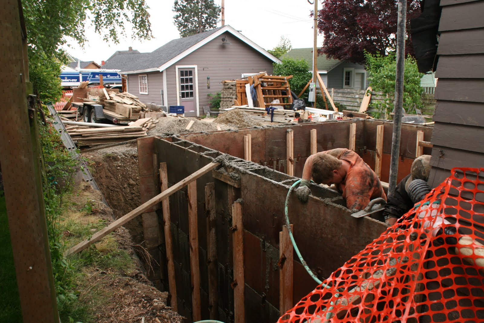
The pump truck and cement mixer arrive for the final big pour of the project.


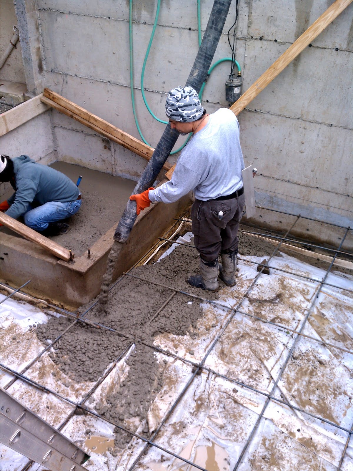
The pump truck operator positions the pump hose for the slab pour.


Pouring the slab at the base of the elevator shaft.  Most of this day's photos were taken by Susan while we were still in Berkeley and Davis.  Thank you, Susan.


Our thanks to Dylan, who sent us this photo.  The elevator floor slab is being finished, and the pour is now moving to the main basement floor slab.


a  nice close-up taken by Susan

In this photo, taken by Susan, Dylan is in the right background, the pump truck operator is standing on the ladder, and one of the two cement finishers is pouring the main slab.


Another Susan view of pouring the main slab.  Yes, the ladder was pulled up before the pour was completed, and yes, the cement guy was able to escape through an opening not visible at the bottom of the photo.


Ditto


Another Dylan photo--finishing the main slab

The finished slab.  Everyone held their breath, waiting for leaves, twigs, or maybe even an errant squirrel to fall on the fresh cement from the trees above, but there were no mishaps.


This photo of the finished slab shows the sump in the northwest corner of the basement.  The slope of the slab was structured so that any water in the basement flows to this corner.


A couple of days later, the crew backed a cement truck into our backyard and poured cement into 5 gallon buckets, which were carried down the ladder to pour the last remaining parts of the basement--the steps leading to the old basement, just to the left of center in this photo, and the remaining two foundation walls of the elevator shaft.  Those two items, together with one additional footing that was added in the old basement, completed the Big Pour.


Close-up of the completed elevator shaft foundation


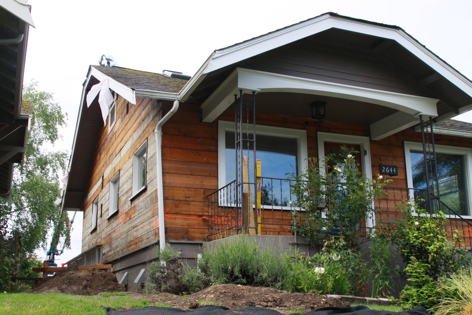
The north and east elevations of the house just before commencement of the installation of new structural posts and shear walls.


At the left in this photo is the new post on the west elevation of the house.  After tying down this post, a shear wall, consisting of half inch plywood, will be applied to the face of the wall.  This post is one of ten new posts that will provide the main support for the second story, and the shear wall at this location is one of eleven shear walls being installed in the house.


This is the south end of the west elevation of the house--on the right of the photo is another post, and a shear wall will be installed at this location, as well.


Another post at the northwest corner of the house


Another view of the post at the northwest corner; a shear wall also will go here.  Note the large metal bracket at the base of the post and a similar bracket at the base of the stud opposite the post.  These brackets are part of a mechanism that ties the entire house to the foundation.  See close-up in next photo.


This is a close-up of the tie-down bracket described above.  The large bolt extends through the plate down into the crawl space, where it is attached to a bracket bolted into the side of the foundation.


Another post and shear wall on the east elevation of the house.  The two large windows nearest us in the photo are the living room windows.


The post at the northeast corner of the house.  All of the posts are 4x6 cedar timbers.


Another shear wall will be installed here at the east end of the north face of the house


One of two interior posts.


At last, our inaugural stud wall!  The wall is structured to the right of the steps.  The plywood above and to the left of the steps is temporary covering, closing that opening for safety reasons.  But the wall you see to the right of the steps is a complete stud wall, the lower portion of which is covered by shear wall material.  This wall officially launches the framing stage of our project!


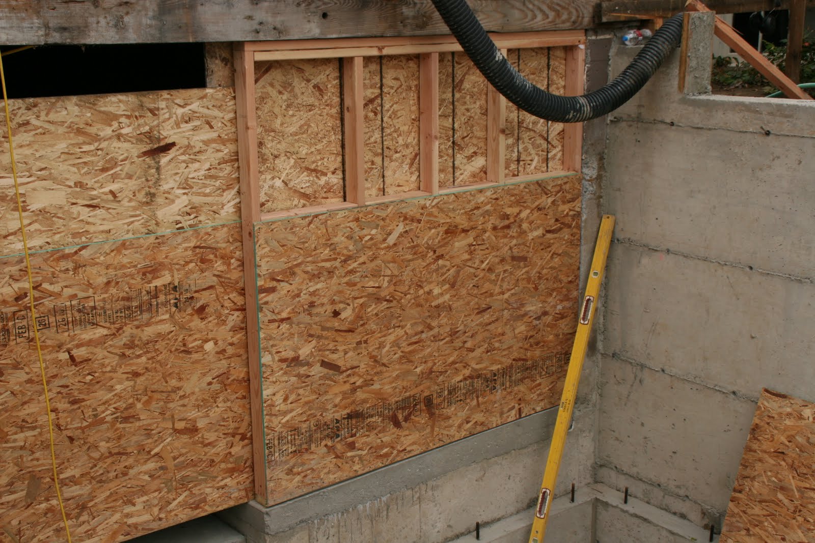
A closer look at our inaugural stud wall


Close-up of a portion of the shear wall, which shows both the shear wall material and also the closely-spaced nailing that adds lateral strength to the shear wall structure.


The white box beam in this photo is one of two beams that support the original roof over our front porch.  If you look closely at the left end of the box beam, you will see that the geniuses who built this in 1925 decided to attach this structural member to the house siding, rather than to a structural part of the house.  Amazingly, the porch roof has weathered the years, including loads of winter snow, without incident.  The temptation is to think that we may have discovered a useful new engineering concept.  Upon reflection, we have decided to fix the structural anomaly before putting the front of the house back together.


Before the commencement of this project, this was our bedroom.  The previous owners of the house had constructed stairs to the attic and had finished the attic with carpet and drywall.  All of these finishes are now lying in a heap, waiting to be recycled when the roof comes off in about two weeks.


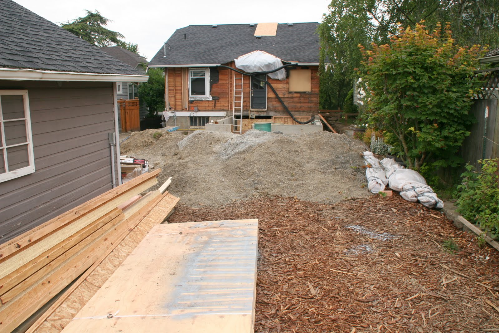
The rear of the house and yard as they looked at the end of the week.  The most exciting addition to the yard are the framing materials shown in the lower left corner of this photo.


The front (north elevation) of the house as it looked at the end of the week.  Our engineer, Jason Bourne, has added his sign to the front lawn.  He has earned the advertisement--as you have already seen, there is a ton of engineering in this project, with much more to come.


Ditto


Ditto


Monday, June 18, 2012

Week 7: While We Were Gone------

During week seven, we were away in San Diego hosting our annual family vacation.    For this week's photos, we are indebted to Luther Allen, our designer, who took thirteen of these photos, and Dylan Hicks, our on-site superintendent, who took the other two.  This photo shows removal of the existing siding from the house.  Containment procedures were required because the existing siding contains lead.


Ditto

Ditto.  This photo also shows the exterior sump (the aqua green tube) and pea gravel that arrived prematurely to the site (more on this below).


In the upper left of this photo, siding removal is still underway.  In the lower right corner, two sections of old clay drain pipe can be seen.  The photo also shows that some gravel backfill has been placed by the excavator into the trench next to the foundation.  More on this below.


This photo has an additional view of the gravel backfill added by the excavator.  This backfill was supposed to be added only after the basement floor slab had been poured.  This produced some excitement for a couple of days, but we received good news from our engineer.  Thanks to a special fast-setting formula that our contractor had prescribed for the concrete used for the basement walls, the basement walls turned out to be strong enough to tolerate the early partial backfill.  The hose-like line running through the center of the photo is our main water line.


another view of the partial backfill


Inside the new basement walls, the gravel is laid down as a base for the floor slab (to be poured next week).  The square in the lower right hand corner of the photo is a portion of the foundation for the elevator shaft.  The notch in the foundation in the center of the photo is where there will be two steps leading from the new basement slab to the slightly higher existing slab of the old basement.


This is the exterior sump, 24 inches in diameter, that will receive water from our new drainage system and pump it to the front of the house down the new drainage pipe to the storm sewer in South Park Drive.


  As you can tell, we just love sumps.  We already have a small sump near the crawl space of our existing basement.  The previous photo shows the new 24" exterior sump we're adding for our rain and ground water drainage system.  This photo shows an 18" diameter sump we are adding at the low point in the new basement slab to pick up any spilled or seeping water in the new basement and pumping into the sewer. 


Dylan took this, and the following, close-ups of the new 18-inch basement sump.  This photo shows the inside of the sump with a water primer connection and electrical box into which the electric pump will be connected.  The bottom of this sump is sealed off.  The theory is that this sump is not primarily for gound water but  for water that might spill in the basement, for example, soapy water from the washing machine.  Since there is the potential for soap and other such substances to be in spilled water, the sump must pump into the sewer rather than the storm drain.


This is Dylan's photo of the outside of the 18-inch basement sump.  The photo also shows the water connection, the electrical conduit, and in the right center of the photo, the sewer connection.

This photo shows preparations for the pouring of the new basement slab.  The white sheet laying over the pea gravel is a 6 mil polyethylene vapor barrier, on top of which the steel rebar has been laid.  Still yet to be formed are the final two sections of the foundation for the elevator. 


A view of the east side of the house showing the partial backfill along that side


A view of the southwest corner of the house showing the partial backfill, completion of siding removal, and repair of the electrical conduit line that carries electricity to the garage and was broken during the excavation process


A view of the rear of the house taken near the end of the work day on Friday


Friday, June 8, 2012

Week 6-The Big Pour

Getting the forms built in preparation for the pour of concrete for the new basement walls.


As you can see, the forms are pretty massive.


We never found out for sure, but we think this guy is spraying non-stick liquid on the forms and form hardware so that they'll come off easily after the pour.


In addition to pouring the walls for the new basement, a shear wall foundation in the existing basement had to be reinforced..


Rebar in one of the nine basement footings


Here come the concrete rigs--the pump truck and the cement mixer, one of two required to do the pour.


Do you think it's going to rain?  Actually, it's the pump truck guy bringing his pump beam across our yard and to the pour site.  The two guys on the right and the orange shirt on the left are the cement guys.  The guy in green is from GeoTest, who took samples of concrete to verify how quickly the concrete would set up and be ready for backfill.

Getting ready to begin the pour, as Sandy, Susan, Maya, and Zoe look on.


peanut gallery


It was a fascinating process.


More of the peanut gallery--two sparrows, very curious about the proceedings.


Another of the nine footings shown from the outside.  At the top of the photo, the old clay pipe is a remnant of what functioned in 1925 as a foundation drainage system.  One of our neighbors says that a similar system at her house seems to be still working.  Not so at our house.  Our best guess is that at our house the clay pipe system stopped working some time in 1926.


Steve Gregory makes sure the concrete ends up where it's supposed to go.


additional footing in the existing basement space


Pouring the footings in the crawl space was a particularly unpleasant and daunting task because there was virtually no head room.  We were impressed that Steve, the head man, did most of the grunt work himself.


Ditto


Ditto


The guys were really happy when this part of the job was done.


On the left a second cement truck arrives.  The first truck carried 10 yards.  The second truck also carried 10 yards--making a total of 20 yards for today's pour.  That's a LOT of concrete, and we used every drop of it.


beginning to pour the walls of the new basement


The physical strength involved in a job like this is really amazing!


more of the pour


Steve and his assistant make sure the concrete goes exactly where it's supposed to go.  Steve handled the concrete pump hose, his assistant followed with an electric vibrator to make sure that the concrete was fully seated in the form.


Granddaughter Maya spent the whole time watching the pour with us.  She learned and retained the name of every single worker on the project and had a keen eye on what was going on.


Can I come and watch the next pour, Grandma?


the pour continues


getting toward the top


BBB site manager,  Dylan, makes sure things have gone according to plan.


Dylan has a good eye for detail and doesn't leave anything to chance. The elevator foundation pour was especially tricky, and Dylan carefully checked the engineering plans as the pour proceeded.


Finishing up. The square in the lower right corner of this photo is the base of the elevator shaft.


finishing the pour around the elevator encasement

ditto

These are the test cannisters that GeoTest filled during the course of the pour.  In seven days they break down one or two of these cannisters, the others follow later.  It all tells us when it's safe to backfill the new basement walls.


This is one of three cracks in the existing foundation that were repaired by Foundation Restoration through the application of epoxy under pressure.  The light gray material running vertically is surplus epoxy that has bled from the crack.  Each of the red dots is the end of a hollow tube that was inserted in the crack and through which epoxy was applied under pressure.  An amazing process that closed these cracks up beautifully.


new shear wall foundation in the basement crawl space


Note the perforated pipe and the water stop drainage material which will help ensure that we have a dry basement from now on.


This is what the new basement space looks like from the outside when the forms have been removed.  It looks like a rather small box, but it's really large enough for a washer, dryer, and various storage components, plus the elevator.  Note the cut-outs--the two cut-outs in the foreground are for windows, the third cut-out in the right rear is for the base of the exterior access door to the elevator. 


Dylan applies an asphalt substance as an additional guard against water seepage.


Over the asphalt, we are applying "delta drain" material--a combination of dimpled PVC-like material and a fabric that captures any seeping water and causes it to flow to the foundation drain at the base of the wall.


asphalt and "delta drain" on all sides of the structure


Additional pipe and hose for the drainage system have arrived.


The sump pump arrives--one of the critical components in ensuring we have a dry home environment. It's 24" in diameter and 11 feet deep.  Water from a variety of foundation drains will drain into the sump, and there will be both a primary and a secondary sump pump pumping the water into a tightline flowing to the city storm drain on South Park Drive.


In this photo and the next one are some rules and restrictions posted in the front and back of the house by Dave and Dylan to ensure that sub-contractors and others involved in the process have consideration for our neighbors.  We regret that one of our neighbors has been awakened at an unseemly early hour on two occasions since the beginning of the project, and Dave and Dylan are really trying hard to enforce some ground rules that will prevent such intrusions on our neighbors.


We're off on vacation for the next 12 days, so there won't be a posting next week.  We'll resume when we return.