Sunday, September 2, 2012

Week 18: Wired, Braced, and Insulated

Last week we showed you what a double crew of electricians looked like when they failed to show up.  This photo shows what a double crew of electricians looks like when they all show up and park in the back of our house.  All five vehicles in this photo brought electricians to the job bright and early on Monday morning, and they worked at warp speed for the next three days.


This is a portion of the crew.

Each of these wires is a "home run," meaning a main wire leading from this space in the basement (which will house the main electrical panel) to various points in the house where it forms a circuit and takes on lighting, outlet, or appliance electrical loads. We're told that someone knows where each of these wires goes.  Neither the BP nor the BB has a clue.


Some of the home run wires rise from the basement up through this exterior wall into the upper story.  Some white and blue wires visible in the upper left corner of this photo comprise part of the data/TV/telephone cabling, which is also being done by the electricians and also involves running "home run" wires from a basement TV/data/phone main panel to the first and second stories of the house.  The mast for the main electrical service is to be installed on this exterior wall, just to the right of the blue ladder.  In order to ready the wall for that installation, the electricians had to complete the "home runs" that run through this wall, then the general contractor needs to insulate the wall and install siding on the wall.  After all that, the main electrical service mast can finally be attached to the building.


This is what a City electrical inspection looks like.  The man in blue on the left is the City inspector; the man on the right is Vladimir, the electricians' crew chief.  This inspection was limited to the wires that run through the exterior wall.  We passed the inspection with flying colors, which gave us a green light to install insulation and siding for that wall, in preparation for the installation of the main electrical mast.


The same exterior wall with insulation in place.


Insulating the "home run" wall kicked off a general commencement of insulation throughout the house.  The applicable principle, apparently, is that if you see a space, you fill it with insulation.  Where exterior walls have been opened up on the outside, batt insulation is applied from the outside as shown in this photo.  Where the walls are closed on the outside but open on the inside, batt insulation is applied from the inside.  In a few cases, we have walls of the original house that are closed both on the inside and outside.  In those cases, we are cutting holes in the outside wall and blowing insulation into the holes.


The upper part of this photo shows the roughly 6" gap between the top of the ceiling of the original house and the bottom of the laminated beams that support the second story.  These gaps are painstakingly filled with batt insulation.  Both the BB and the BP wholeheartedly support the energy policies that require all this insulation, but there is an irony to this.  Both the BB and the BP love fresh air in the house, and so probably will have a lot of windows open most of the time, even in winter.

This is not a private performanace by Cirque du Soleil, but a routine method that the insulation crew has for efficiently installing insulation in high places.


Ditto.


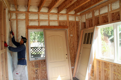
Applying batt insulation in the new dining room.  Also visible in the photo are two of our new exterior doors.  The door on the left will be the exterior door providing ground level access to the elevator; the door on the right will be the entry door from the back porch to the dining room.  Both doors are fiberglass.


The BB looking over her office after the insulation has been added to all the walls..  With insulation in place, spaces that formerly seemed open with just a suggestion of the outlines of a room, now become full-blown rooms.


The BP's office with the walls insulated.


The library with the walls insulated


The second floor stop for the elevator with the walls insulated.  This space is really starting to look like an elevator will be living there.


The BP wondering what time the elevator will arrive.


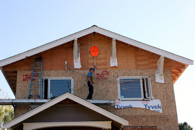
Another exciting development this week has been the installation of the four "knee braces," which have been fashioned out of 6x6 timbers.  Chris was given the assignment of installing these important architectural details.  Each knee brace weighs between thirty and forty pounds and, as you can see in the photo, they are installed at the very top of the house some thirty plus feet above ground level.  This photo shows the first two knee braces installed and also shows the scaffolding set-up that Chris devised for those two braces.


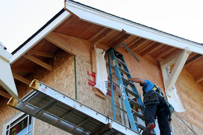
This photo shows the work in progress after installation of the third knee brace.  To get the third knee brace in place, Chris worked from the blue ladder that you see in the photo, which rested on the scaffold held in place by the long aluminum ladder.


Before Chris started on the 4th knee brace, we interrupted him and asked him to hold up mock-ups of a louvered vent that will be installed approximately where Chris is holding it in this photo.  (No--it won't be orange).  In this photo we took a look at a vertical presentation.  In the next photo, we tried a horizontal presentation.


Here is the horizontal presentation.  We invite blog watchers to guess which presentation we chose.  At the end of the project, the blog watcher with the cleverest response may (if it's still on the premises) win the orange oval.  On a more serious note, this photo also shows, clearly, an important part of Chris's safety gear that he used throughout his work on the scaffolding.  He is wearing a full body harness attached by mountain climbing rope to the sturdy steel ring that is firmly bolted to the house (just to the left of the third knee brace in this photo.)  We have been very impressed by how safety conscious Bellingham Bay Builders have been throughout this project, and this is just one of many examples.


While Chris prepared for installation of the 4th knee brace in the front of the house, Dylan climbed a 30' ladder in the back of the house to give us a look at both the vertical and horizontal presentations of a slightly smaller louvered vent that will be installed on this exterior wall.


Ditto


Back in the front of the house, Chris is using a carpenter's square and a level to install a jig that will enable him to lift the knee brace into place in exactly the right position. 


This photo shows the completed jig.  There are 2x4s installed vertically that will frame the exact vertical positioning of the knee brace, and there is a 2x6 installed at the bottom of the jig that serves two purposes--it defines the bottom line of the installed knee brace and it also forms a ledge upon which the knee brace can be rested once it's lifted into place.  This will enable Chris to hold the knee brace in place with one hand and install holding lag screws with the other hand.

Chris is moving the 4th knee brace over to to the scaffolding from where he will lift it up into the jig.


Lifting the knee brace into the jig.


A broader view of Chris's activity showing where he was in relation to the ground.  This work is not for the faint-hearted.


Chris installs a holding screw that will hold the knee brace in place while the main lag screws that secure it firmly to the building will be installed from inside the house.


Chris gets out the level again to make sure that the knee brace is plumb.  In this case, some minor adjustments were needed but quickly completed.


When Chris was satisfied that the knee brace was in exactly the right position, he alerted Dylan, who had climbed into the attic and was prepared to install several 10" lag screws to permanently secure the brace to the building.

Dylan is installing an additional 10" lag screw at an angle to make sure that the entire lag screw winds up inside the knee brace.  The tool that he's using is one of several miracle tools that we've been introduced to during the course of this project.  A 10" lag screw requires an enormous amount of torque to go all the way in even though the wood is relatively soft.  An ordinary rotary drill would work only if there were a fairly large pilot hole (which would reduce the grip of the screw).  Otherwise, an ordinary rotary drill would get the screw part way in, where it would bind, and continued operation of the drill would strip the head of the screw.  The tool that Dylan is using is a pneumatic drill operated by compressed air, which creates a pulsating action that provides the necessary torque without stripping the head of the screw. 


Looking southeast towards the house after all knee braces have been installed.

This photo provides textbook evidence of the importance of double checking work in progress regardless of how sure you are about the design of what's being built.  In this photo the BB is standing in the shower enclosure.  The walk-in opening to the shower has been framed so that it is about 34" in width and is situated at the rear of the shower.  This was not a mistake by Dylan.  This was exactly what was drawn in the floor plan and is a detail that we reviewed and approved multiple times during the various stages of development of the final floor plan.  Our intent all along has been that the shower opening be about 24" wide (after application of the tile) and located at the front of the shower.  In these details we are essentially copying the shower that our daughter Susan and her husband Chris built in their house, the design of which has been very successful.  It was not until Dylan actually framed the wall that we realized that all these many months we have been looking at one design and inexplicably assuming that it was a different design.  Fortunately, catching this difference now means a very simple change in framing.  Discovering it later would have been much more problematic.


Still another very exciting development this week was opening the wall between the kitchen and the new dining room.  This photo, taken several weeks ago, shows how the wall looked before it was opened up.  For the change, see the next photo.


This is a photo taken from the kitchen, looking into the dining room.  The kitchen is small and has only one small window with frosted glass (to protect the privacy of our neighbors).  If the kitchen were fully enclosed it would be quite dark.  Opening up this wall brings in a lot of light from the dining room windows and also provides a view from the kitchen into the rear yard, which we think will be quite pleasing.


This photo shows the same opening viewed from the dining room into the kitchen.


It was an exceptionally clear day and we couldn't resist taking this photo of Bellingham Bay from the bedroom window.  This is what realtors probably would call a "filtered" view of the bay, but it is enough to create a feeling of connection between us and the bay, and we enjoy that feeling.


As a harbinger of things to come, perhaps as early as next week, this photo shows one of several bundles of siding that have arrived on site. 


This photo shows a bundle of shingles that will be installed as siding material in the upper 25% of the house.  Next to the bundle of shingles are rolls of building wrap.  This material, which is ribbed to allow vertical water drainage, will be applied to the exterior of the house prior to installation of the lap siding and shingle siding.  With any luck, next week will be a week of very visual changes on the outside of the house.

No comments:

Post a Comment